In this application, we will practice day and night
with LDR. It will also be a night light application. We learned how to measure the value of LDR in the previous lesson. Now, after reading these values, we
will both automatically flash the led and make a short application in the
Mblock program.
Let's come to the circuit elements:
1-Arduino Uno (1)
2-BreadBoard
3-220Ω Resistor(2 pcs)
4-Led (1 )
5-LDR (1)
6-Jump Cables
We need supplies.
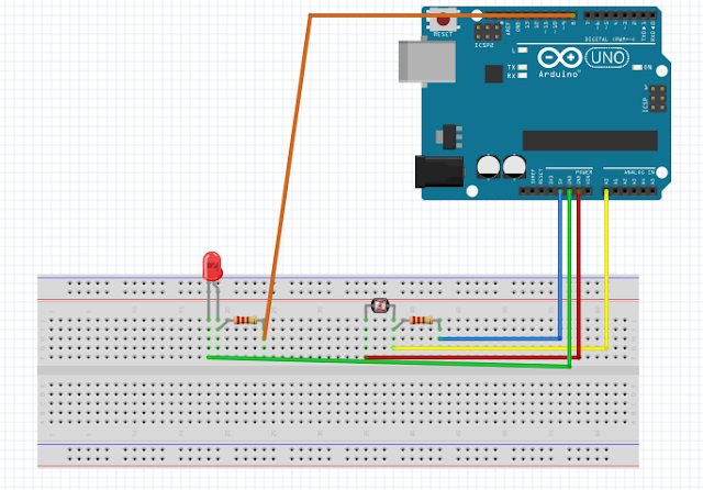
Our circuit diagram is as follows.
We connect a 220 ohm
resistor to one leg of our LDR. We connect a cable to one leg of the resistor
we connected and connect this cable to the 5 volt pin (blue cable) We connect
the other leg of the resistor we connected to one leg of the LDR to the analog
pin A0 with a cable (yellow cable) (Here is one leg of the LDR, one leg of the
resistor and the cable is the same at the bottom. We connect it to the other
free leg of the LDR with a GND (- terminal) cable. Let's connect a 220 ohm
resistor to the long leg of the led we added. Let's connect one leg of this
resistor to our digital pins with a cable. Let's connect the GND (- Terminal )
with the cable from the other leg of the LED and finish our circuit.
Thus,
we have prepared our circuit. It's time to write our code.
City
with water (The dark one) city with water 2 (The bright one) in the Mblock
library as a new backdrop
I
added one sprite to the scene.
The code part is as
follows:
When the green flag is clicked,
we must first read the value on the A0 analog pin. To transfer this value to a
variable, I first create a variable for the Light value from the Data&Block
menu. To transfer the light value to this Light value variable, I place the A0
analog pin read command from the Robots menu into the Light value variable. If
the light value is lower than a certain amount, let it be Day, otherwise Night.
For this, I get the command if not from the control menu. Let's do the if part
first. I get the small transaction code from the action menu I insert it into
your code. I'm placing the light value data on one side of this smaller code.
In the other part, I write a light value. I found that if it is very bright in
my environment, I found that the light value drops below 700, so I determined a
number like 750. If the light value is lower than 750, let the decor change and
the bright one come. Add this toggle code from look menu to .....decor. I
choose the decor that is bright. And I connected my led and I do not light the
digital pin low (I added this code from the robots menu). If. If this value is
greater than 750, the backdrop scene decor will change and a darker decor will
come. And by making the led on the digital pin high, we will make it light up.
Then the night will come. In fact, this application we have made can also be
referred to as a night light application with LDR. The only difference is that
we didn't just turn on and off the led. We made a small decor change using
mblock.
In order to run these
codes, after connecting our arduino board and circuit to the computer with a
usb cable, we first select the Serial port from the Connect menu, then select
the port to which our arduino board is connected. After selecting it, we will
have sent the codes we wrote with the firmware update to our arduino board from
the connect menu again. Thus, our program becomes ready to run.
Note: If you keep the
light on the LDR, the light value will decrease, if you cover the LDR, the
light value will increase.
To
download the source code of the program CLICKHERE
First of all, we add the
upload mode broadcast extension for each part from the extensions section. Thus,
we can enable interaction between the arduino uno card and the sprites or the background.
We add 2 day and night of the backgrounds to the scene and sprite.
We create a variable called light value. When our arduino
uno board starts to work, let the value of this variable be 0. Then the value
read from LDR is assigned to this variable. If the value of our variable is
lower than 750, our led will turn on and the message will have a value of 1,
which will send a message to interact with the sprite and the background. If the
value of the variable is not less than 750 our led will turn off and the
message will have a value of 0 which will send a message to interact with the
sprite and the background.
If the value of the message from the arduino uno card part
is 1, sprite will say "Night Time", otherwise, it will say "Day Time".
If the value of the message from the arduino uno card part
is 1, make the background of the scene the night background, otherwise, make it
the day background.
For All Scratch Examples CLICK HERE
For Mblock With Arduino Examples CLICK HERE


Comments
Post a Comment